Seismic Repair & Strengthening of Masonry Walls (URM) with FRP
Glass and Carbon FRP provide unique solutions for repair and strengthening of unreinforced masonry (URM) walls. Both flexural and shear capacity of masonry walls can be enhanced by applying thin films of glass or carbon FRP to the exterior surface of the wall using QuakeWrap's patented technology.
Among the advantages of Fiber Reinforced Polymer (FRP) are:
- Increases out-of-plane flexural strength
- Increases in-plane shear strength
- Increases stiffness at service loads
- Results in monolithic action of all units
- Converts masonry from a weak/brittle material to a strong/ductile material
- Strengthening of entire wall can be accomplished by treating only a fraction of wall surface area
- Adds very little weight to the wall
- Increases wall thickness by less than ¼ in. (5mm)
- Limited access requirements
- Costs less than conventional methods
How Does the Retrofit and Strengthening Work?
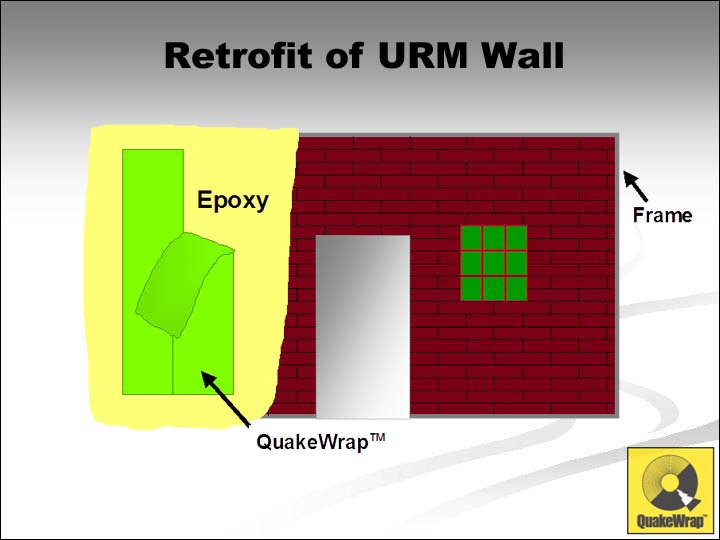 A
layer of epoxy is applied to the wall surface. Carbon or glass FRP fabrics saturated with Saturating Resin are applied in strips to the wall
surface. The fabrics add tremendous flexural and shear strength to the
wall and force all masonry units to work as a monolithic wall. If desired,
the wall can be painted, stuccoed or covered with other cosmetic materials.
A
layer of epoxy is applied to the wall surface. Carbon or glass FRP fabrics saturated with Saturating Resin are applied in strips to the wall
surface. The fabrics add tremendous flexural and shear strength to the
wall and force all masonry units to work as a monolithic wall. If desired,
the wall can be painted, stuccoed or covered with other cosmetic materials.
Research and Development
The principals of QuakeWrap, Inc. were the first research team in the U.S. to receive two grants from the National Science Foundation (in 1992 and 1995) to study the behavior of their patented technology (U.S. Patent #5,640,825). A large number of URM wall specimens have been constructed and tested under simulated earthquake loading. The findings of this extensive study have been published in several technical papers as indicated below.
Flexural Behavior
 The
flexural strength of URM walls is limited by the tensile strength of the
mortar, which in most aging structures is very small. When QuakeWrap™
is bonded to the exterior surface of the wall, it provides a large tensile
component that, along with the compressive strength of the masonry, can
resist large moments.
The
flexural strength of URM walls is limited by the tensile strength of the
mortar, which in most aging structures is very small. When QuakeWrap™
is bonded to the exterior surface of the wall, it provides a large tensile
component that, along with the compressive strength of the masonry, can
resist large moments.
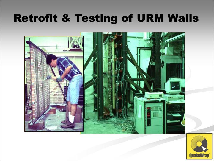 Single-
and double-wythe wall specimens ranging in height from 28 in. to 120 in.
were constructed of clay bricks and were reinforced with glass fabric
that covered 7% to 100% of the wall surface area. The walls were subjected
to cyclic uniform surface pressure.
Single-
and double-wythe wall specimens ranging in height from 28 in. to 120 in.
were constructed of clay bricks and were reinforced with glass fabric
that covered 7% to 100% of the wall surface area. The walls were subjected
to cyclic uniform surface pressure.
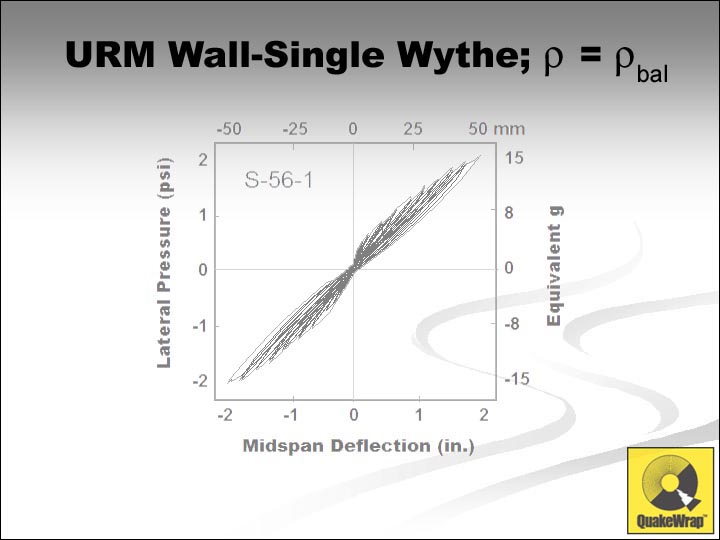 Typical
hysteretic response of a 56-in. high wall is shown here; the mid-height
deflection of the wall was over 2½ inches and it resisted loads
more than 12-times its own weight. These values are considerably higher
than the minimum code requirement performances.
Typical
hysteretic response of a 56-in. high wall is shown here; the mid-height
deflection of the wall was over 2½ inches and it resisted loads
more than 12-times its own weight. These values are considerably higher
than the minimum code requirement performances.
 All
specimens failed in a ductile manner after carrying significantly large
loads at high displacement levels. As shown in the slide, in general,
the higher the amount of QuakeWrap™ coverage, the larger the lateral
load resisted by the specimen. Detailed findings of this study are discussed
in ASCE and ACI Journal articles covering Behavior,
Out-of-Plane
Response, and Modeling
of retrofitted walls.
All
specimens failed in a ductile manner after carrying significantly large
loads at high displacement levels. As shown in the slide, in general,
the higher the amount of QuakeWrap™ coverage, the larger the lateral
load resisted by the specimen. Detailed findings of this study are discussed
in ASCE and ACI Journal articles covering Behavior,
Out-of-Plane
Response, and Modeling
of retrofitted walls.
Shear Behavior
 In
concrete or masonry structures, shear is resisted as diagonal tension.
When Fiber Reinforced Polymer (FRP) is bonded to the URM wall with fibers
aligned in horizontal and vertical directions, a shear crack cannot cause
failure until all fibers crossing that crack fail in tension. Similar
to the design of R/C walls, where the reinforcement is placed in vertical
and horizontal directions, retrofit of URM walls for shear requires that
biaxial QuakeWrap™ fabrics be used.
In
concrete or masonry structures, shear is resisted as diagonal tension.
When Fiber Reinforced Polymer (FRP) is bonded to the URM wall with fibers
aligned in horizontal and vertical directions, a shear crack cannot cause
failure until all fibers crossing that crack fail in tension. Similar
to the design of R/C walls, where the reinforcement is placed in vertical
and horizontal directions, retrofit of URM walls for shear requires that
biaxial QuakeWrap™ fabrics be used.
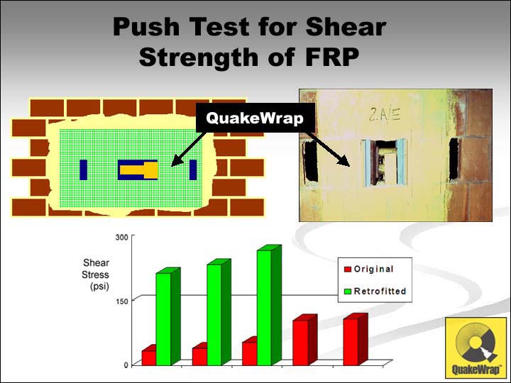
 To
simulate the effect of shear strengthening, "push" tests were conducted
in the laboratory. Three bricks were placed against each other as shown
in the slide. To discount the strength of mortars, no mortar was used.
However, to account for the detrimental effect of the space between the
bricks, pieces of lubricated spacers were placed between the bricks to
simulate the mortar joint. Such specimen would have zero strength in shear.
However, with bonding a 4.5 x 8.0-inch 10-oz QuakeWrap™ fabric on
the front and back faces of the subassembly, the specimens carried loads
in excess of 4000 lbs. Placing the fibers at 45/135 degrees increased
the stiffness of the system but the ultimate load remained about the same
as when the fabric was placed at 0/90 degree orientation. More detailed
information about this study is presented in an ASCE
Journal Article.
To
simulate the effect of shear strengthening, "push" tests were conducted
in the laboratory. Three bricks were placed against each other as shown
in the slide. To discount the strength of mortars, no mortar was used.
However, to account for the detrimental effect of the space between the
bricks, pieces of lubricated spacers were placed between the bricks to
simulate the mortar joint. Such specimen would have zero strength in shear.
However, with bonding a 4.5 x 8.0-inch 10-oz QuakeWrap™ fabric on
the front and back faces of the subassembly, the specimens carried loads
in excess of 4000 lbs. Placing the fibers at 45/135 degrees increased
the stiffness of the system but the ultimate load remained about the same
as when the fabric was placed at 0/90 degree orientation. More detailed
information about this study is presented in an ASCE
Journal Article.
 In
addition to the above laboratory studies, a field investigation of the
system was carried out in 1995. The San Francisco City Hall Building was
undergoing seismic retrofit in the mid-1990s. The basement of this building
included a number of hollow-clay tile walls that were weak in shear.
In
addition to the above laboratory studies, a field investigation of the
system was carried out in 1995. The San Francisco City Hall Building was
undergoing seismic retrofit in the mid-1990s. The basement of this building
included a number of hollow-clay tile walls that were weak in shear.
 Five
push tests had been already carried out by an independent laboratory (Schwein/Christensen
Laboratories, Inc., Lafayette, CA) to determine the shear strength (capacity)
of the existing walls. The results of each test is shown on the graph
to the right. These tests had indicated an average shear strength of approximately
64 psi. The project engineer (Ms. Simin Naaseh of Forell/Elsesser
Engineers Inc, San Francisco) had concluded that these values were
too low and consequently the walls were scheduled to be torn down by the
contractor.
Five
push tests had been already carried out by an independent laboratory (Schwein/Christensen
Laboratories, Inc., Lafayette, CA) to determine the shear strength (capacity)
of the existing walls. The results of each test is shown on the graph
to the right. These tests had indicated an average shear strength of approximately
64 psi. The project engineer (Ms. Simin Naaseh of Forell/Elsesser
Engineers Inc, San Francisco) had concluded that these values were
too low and consequently the walls were scheduled to be torn down by the
contractor.
It was decided that some of these walls be retrofitted with QuakeWrap™ and be tested to determine the potential gain in shear strength due to such retrofit.
 Fabric
Reinforced Polymer and epoxy resins were shipped to the same laboratory
that had conducted the initial push tests on the walls. This was done
to ensure impartiality of the results. Glass fabrics were bonded to both
front and back faces of some walls and the walls were subjected to push
tests; three such tests were carried out. The results shown in green bars
demonstrate that the retrofitted walls resisted average shear stresses
of nearly 240 psi. The mode of failure in all cases was the puncturing
of the hollow clay tiles under the contact with the jack head. Clearly,
if the masonry units were solid, even higher shear values could be achieved.
Fabric
Reinforced Polymer and epoxy resins were shipped to the same laboratory
that had conducted the initial push tests on the walls. This was done
to ensure impartiality of the results. Glass fabrics were bonded to both
front and back faces of some walls and the walls were subjected to push
tests; three such tests were carried out. The results shown in green bars
demonstrate that the retrofitted walls resisted average shear stresses
of nearly 240 psi. The mode of failure in all cases was the puncturing
of the hollow clay tiles under the contact with the jack head. Clearly,
if the masonry units were solid, even higher shear values could be achieved.
Case Studies
A number of buildings have been strengthened using QuakeWrap™ products. A sample of projects are listed below. By clicking on each project, you will be able to view specific information on each project.
- One-Story CMU Block Building, Glendale, CA
- Two-Story Masonry Building, Redwood City, CA
- United Airlines Building, Oakland International Airport